

Product
Product Details
Brass CET Glands
Brass CET Glands – Central Earth Termination Cable Glands
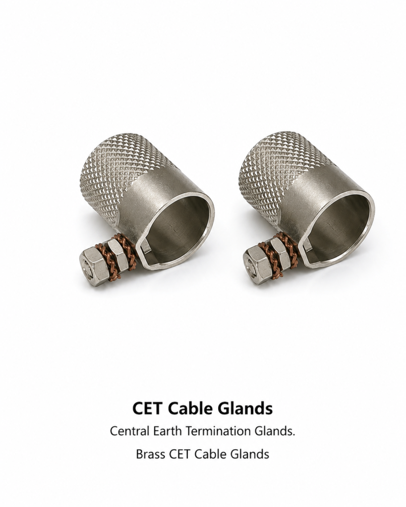
Brass CET glands (Central Earth Termination cable glands) are specialist single-compression armoured cable glands that provide a direct, integral earth bonding path from the cable armour to the metalwork of the electrical enclosure through a single-piece gland body — without requiring a separate earth tag, earth wire, or external earthing device. Manufactured by Electrical Accessories India at our Jamnagar precision machining facility from free-machining brass alloys conforming to IS 319, CW614N, and CZ121, CET glands are the engineered solution for earthing armoured cables in power generation, industrial switchgear, motor control centres (MCCs), offshore platforms, and any installation where armour earth continuity is mandated by IEC 60364, BS 7671 (18th Edition), or IS 3043. Available in metric thread sizes M20 to M63 and NPT 1/2″ to 2″.
Price: US$ 15.50 per kilogram (Ex-works Jamnagar, India). Contact sales@elecaccs.com for volume pricing and project quotations.
Product Overview
What Is a CET Cable Gland?
A Central Earth Termination (CET) gland is a single-compression cable gland specifically engineered for steel wire armoured (SWA), aluminium wire armoured (AWA), steel tape armoured (STA), and aluminium tape armoured (ATA) cables where the cable armour must be electrically connected (earthed/bonded) to the enclosure at the point of cable entry. Unlike standard A-type (unarmoured) or BW-type (armoured, no integral earth) glands, the CET design incorporates an integral earthing clamp or earth lug within the gland body that makes direct metallic contact with the cable armour wires or tapes, and a dedicated earthing stud (M4 or M5 hex bolt) that connects this internal clamp to an external earth conductor. Related components include: armoured cable glands (BW type), brass lock nuts, earth tags, earth continuity conductors, cable armour clamps, conduit locknuts, and cable gland shrouds. In industry terminology, CET glands are also referred to as: armour earth glands, SWA earth bonding glands, central earthing glands, armour clamping earth glands, CET fittings, and integral earth cable glands.
Design Principles and Earth Bonding Function
The CET gland achieves armour earth continuity through a precision-machined internal cone that compresses over the flared cable armour wires or tapes when the gland is assembled, creating a 360° circumferential metallic contact with the armour conductor. This compression contact provides a low-resistance earth bonding path (typically <0.05 Ω per IEC 62444 earth continuity test) from the cable armour to the gland body, and thence to the enclosure metalwork via the gland thread engagement with the lock nut. The integral earthing stud (M4 or M5 hex bolt with nut and washer) allows an additional external protective earth conductor (PEC) to be connected directly to the gland, satisfying IEC 60364-5-54 requirements for protective earthing and equipotential bonding in electrical installations. This eliminates the need for a separate earth tag, reducing assembly time, installation cost, and potential points of failure in the earth continuity path.
Comparison with Standard BW Cable Glands
Standard BW (Barrier Wire) cable glands provide mechanical anchoring and sealing of SWA/AWA cables but do not incorporate an integral earth bonding facility — a separate brass earth tag or earth locknut must be added to complete the armour earth circuit. CET glands integrate this earth bonding function into the gland body itself, reducing component count from 3–4 parts (gland + locknut + earth tag + external earth conductor) to 2 parts (gland + locknut), significantly simplifying installation in high-density cable entry situations such as MCC cable chambers, transformer termination boxes, and multi-cable panel entries. For installations where both internal and external earth bonding is required (as in ATEX hazardous area zones), CET glands can be combined with additional earth tails. For comparison, see our standard Brass BW Cable Glands and Brass A2 Cable Glands pages.
Cable Compatibility and Armour Types
Brass CET glands are compatible with the following armoured cable constructions: SWA (Steel Wire Armoured) to BS 5467, BS 6346, IEC 60502-1; AWA (Aluminium Wire Armoured) to BS 5467; STA (Steel Tape Armoured) to IEC 60502-1; ATA (Aluminium Tape Armoured); DSTA (Double Steel Tape Armoured) for medium-voltage applications; XLPE SWA cables (BS 5467, IEC 60502-2); and paper-insulated lead-covered armoured (PILCA) cables. The internal armour cone compression mechanism accommodates standard armour wire diameters from 0.8 mm to 3.15 mm as defined in BS 6346 and IEC 60228 conductor tables. For cables with non-standard armour configurations or large-diameter armour wires (>3.15 mm), consult our technical team for CET gland cone selection.
Materials, Alloys, and Corrosion Protection
CET gland bodies are machined from IS 319 Type I free-machining brass (57–59% Cu, 39–42% Zn, 1.5–2.5% Pb), equivalent to CW614N (EN 12164), CZ121 (BS 2874), and UNS C36000. The internal armour clamp insert is manufactured from electrolytic tough-pitch (ETP) copper or brass for high conductivity and corrosion resistance at the armour-to-clamp interface. The earthing stud assembly (M4/M5 hex bolt, plain washer, spring washer, nut) is manufactured from brass IS 319 or nickel-plated brass to prevent corrosion at the external earth connection point. Standard external finish is natural bright brass; nickel-plated finish (electroless, 5–10 µm) is available for corrosive atmosphere Class C4–C5 installations. DZR (dezincification-resistant) brass variants in CW602N are available for marine and coastal applications.
Sealing, IP Rating, and Cable Retention
Brass CET glands incorporate a single-compression sealing system comprising a neoprene (NBR) or EPDM elastomeric sealing ring that compresses around the cable outer sheath when the compression nut is tightened, providing IP54 to IP66 ingress protection per IEC 60529. The cable outer sheath seal prevents moisture and dust ingress at the cable-to-gland interface, while the enclosure panel seal (flat neoprene face seal or O-ring) prevents ingress through the panel entry. Single-compression CET glands are rated IP66 as standard; IP68 variants with enhanced inner sealing are available for submersible or continuously wet applications. Cable retention is provided by the armour clamping action of the compression cone, which also serves as the primary armour earth bonding interface.
SKU Coding System
Electrical Accessories India assigns unique SKU codes to each CET gland variant for order management, project documentation, and traceability. The SKU format is: EAI-CET-[Thread Size]-[Finish]. Examples: EAI-CET-M20-NB (M20 natural brass), EAI-CET-M25-NP (M25 nickel plated), EAI-CET-NPT34-NB (3/4″ NPT natural brass). Full SKU listing is provided in the product variants table below. Custom SKU mapping to customer part numbers is available for OEM and long-term supply agreements.
Regulatory Requirements for CET Earthing
The use of CET glands is often mandated or strongly recommended by the following regulatory frameworks and engineering standards: IEC 60364-5-54 (earthing arrangements and protective conductors); BS 7671:2018 (IET Wiring Regulations, 18th Edition) Regulation 543 (selection and erection of protective conductors); IEC 60079-14 (electrical installations in hazardous areas); IEC 62444 (cable gland performance and testing); ENA (Energy Networks Association) Engineering Recommendations; and site-specific specifications from EPC contractors and utilities including National Grid, SPEN, SSE, EDF, Saudi Aramco, Shell DEP, and Woodside. The CET design satisfies the requirement for armour earth continuity where the armour is used as the protective conductor (PC) or circuit protective conductor (CPC) in TN-S, TN-C-S, and TT earthing systems.
Key Features
- Integral armour earth bonding — no separate earth tag required
- 360° armour compression cone contact — low earth resistance <0.05 Ω
- M4/M5 external earthing stud — connects external protective earth conductor directly
- Metric M20–M63 and NPT 1/2″–2″ thread range
- IS 319 / CW614N / CZ121 free-machining brass body
- IP66 standard; IP68 option available
- Compatible with SWA, AWA, STA, ATA, DSTA armoured cables
- Unique EAI-CET SKU coding for full project traceability
Integral Earth Bonding — Elimination of Separate Earth Tags
The defining feature of the CET gland is the elimination of the separate earth tag, earth locknut, or external earth clamp that standard BW-type glands require. The integral copper or brass armour clamp within the CET body makes 360° contact with the cable armour during compression, and the external M4/M5 earthing stud provides a secure, low-resistance connection point for the external earth wire. This integrated design reduces installation time by 30–50% per cable entry compared to BW + earth tag assemblies, and eliminates the risk of the earth tag being omitted, incorrectly installed, or subsequently loosened during cable pulling operations. See our Earth Tags Brass page for standalone earthing accessories.
Low Earth Resistance Performance
The 360° compression cone design achieves armour-to-gland earth resistance values typically below 0.05 Ω when tested per IEC 62444 Clause 9 (earth continuity test at 25 A for 60 seconds). This exceeds the requirements of BS 7671 Regulation 543.3 (protective conductor resistance) and satisfies IEC 60079-14 bonding resistance requirements for hazardous area installations. The copper insert material at the armour clamp interface minimises galvanic corrosion between the brass gland body and steel or aluminium armour wires, maintaining low contact resistance throughout the service life of the installation.
ATEX and Hazardous Area Compliance
CET glands are suitable for use in ATEX Zone 1 and Zone 2 (Groups IIA, IIB, IIC) and Zone 21 and Zone 22 hazardous locations when installed with Ex e (increased safety) or Ex d (flameproof) certified cable gland assemblies per IEC 60079-14. The integral earth bonding provided by the CET design satisfies the earthing and bonding requirements of IEC 60079-14 Clause 9.3 (earthing and equipotential bonding) without the need for additional external earth bonding fittings. For fully ATEX-certified CET gland assemblies, contact our technical team for certification documentation.
Compatibility with Cable Gland Standards
CET glands are manufactured and tested in accordance with IEC 62444 (cable gland standard), which covers mechanical strength, sealing, temperature cycling, vibration, and earth continuity performance. The thread dimensions conform to ISO 965-1 (metric) and ANSI/ASME B1.20.1 (NPT), ensuring compatibility with standard enclosure panel entries, conduit locknuts, and cable gland accessories from all major manufacturers. Our CET glands are dimensionally interchangeable with CET designs from other manufacturers, allowing drop-in replacement for existing installations. Related products: Brass CW Cable Glands, Marine Cable Glands, Stainless Steel Cable Glands.
High-Density Cable Entry Applications
In electrical installations with 50–200+ cable entries per panel (MCCs, transformer termination enclosures, PLC rooms, substations), the CET gland’s single-component earth bonding approach delivers significant installation efficiency advantages over separate BW + earth tag assemblies. Project experience across power generation, oil & gas, and infrastructure projects demonstrates 25–40% reduction in cable termination labour hours when CET glands replace conventional BW + separate earthing arrangements. This is particularly significant for offshore platform and data centre projects where access restrictions and labour costs are high.
Sealing and Environmental Performance
The single-compression sealing system uses a moulded neoprene (NBR) sealing ring graded for operating temperatures of -20°C to +80°C, with EPDM sealing rings available for -40°C to +90°C low-temperature or outdoor applications. The gland face seal (flat neoprene or O-ring type) achieves IP66 sealing at the enclosure panel interface. For outdoor, coastal, and industrial environments (ISO 9223 Class C3–C5-M), nickel-plated brass CET glands with EPDM sealing provide optimal corrosion resistance and maintain IP66 integrity throughout the design service life. UV-stabilised PVC shrouds from our PVC Shrouds for Cable Glands range are recommended as complementary protection for the cable tail.
Technical Specifications
| Parameter | Specification |
|---|---|
| Gland Type | Single-compression armoured with integral Central Earth Termination (CET) |
| Material – Body | Brass IS 319 / CW614N (EN 12164) / CZ121 (BS 2874) / UNS C36000 |
| Material – Armour Clamp | ETP Copper or Brass IS 319 |
| Material – Sealing Ring | NBR (standard); EPDM (optional) |
| Thread – Metric | M20 to M63, Pitch 1.5 mm, ISO 965-1 |
| Thread – NPT | 1/2″ to 2″, ANSI/ASME B1.20.1 |
| Earthing Stud | M4 or M5 hex bolt + nut + plain washer + spring washer (brass) |
| Earth Resistance (IEC 62444) | <0.05 Ω at 25 A, 60 seconds |
| IP Rating | IP66 standard; IP68 optional |
| Temperature Range | -20°C to +80°C (NBR seal); -40°C to +90°C (EPDM seal) |
| Surface Finish | Natural bright brass; Nickel plated (5–10 µm) optional |
| Corrosion Resistance | 96 hrs NSS salt spray (standard); 200+ hrs (nickel plated) |
| Compatible Cable Types | SWA, AWA, STA, ATA, DSTA, XLPE SWA, PILCA |
| Armour Wire Dia. Range | 0.8 mm to 3.15 mm |
| Standard | IEC 62444, BS 6121, BS 7671, IEC 60364-5-54 |
| Price | US$ 15.50 per kilogram (Ex-works Jamnagar) |
CET Gland Size and SKU Reference Table – Metric
| SKU | Thread Size | A/F Hex (mm) | Cable OD Range (mm) | Armour OD Range (mm) | Earth Stud | IP Rating |
|---|---|---|---|---|---|---|
| EAI-CET-M20-NB | M20×1.5 | 27 | 8–15 | 10–18 | M4 | IP66 |
| EAI-CET-M25-NB | M25×1.5 | 32 | 13–21 | 15–24 | M4 | IP66 |
| EAI-CET-M32-NB | M32×1.5 | 41 | 18–28 | 20–31 | M5 | IP66 |
| EAI-CET-M40-NB | M40×1.5 | 50 | 25–35 | 27–38 | M5 | IP66 |
| EAI-CET-M50-NB | M50×1.5 | 60 | 32–44 | 35–48 | M5 | IP66 |
| EAI-CET-M63-NB | M63×1.5 | 75 | 42–57 | 45–62 | M5 | IP66 |
CET Gland Size and SKU Reference Table – NPT
| SKU | NPT Size | A/F Hex (mm) | Cable OD Range (mm) | Armour OD Range (mm) | Earth Stud | IP Rating |
|---|---|---|---|---|---|---|
| EAI-CET-NPT12-NB | 1/2″ NPT | 32 | 13–21 | 15–24 | M4 | IP66 |
| EAI-CET-NPT34-NB | 3/4″ NPT | 41 | 18–28 | 20–31 | M5 | IP66 |
| EAI-CET-NPT1-NB | 1″ NPT | 50 | 25–35 | 27–38 | M5 | IP66 |
| EAI-CET-NPT114-NB | 1-1/4″ NPT | 60 | 32–44 | 35–48 | M5 | IP66 |
| EAI-CET-NPT112-NB | 1-1/2″ NPT | 75 | 38–52 | 41–57 | M5 | IP66 |
| EAI-CET-NPT2-NB | 2″ NPT | 90 | 48–65 | 52–70 | M5 | IP66 |
Raw Material Grade Equivalents
| Standard | Grade | Cu% | Zn% | Pb% |
|---|---|---|---|---|
| IS 319 (India) | Type I | 57–59 | Bal. | 1.5–2.5 |
| EN 12164 (Europe) | CW614N | 57–59 | Bal. | 2.5–3.5 |
| BS 2874 (UK) | CZ121 | 57–59 | Bal. | 2.5–3.5 |
| ASTM B16 (USA) | UNS C36000 | 60–63 | Bal. | 2.5–3.7 |
| DIN 17660 (Germany) | Ms58 | 57–59 | Bal. | 2.5–3.5 |
| DZR (Marine) | CW602N / CZ132 | 61–63 | Bal. | 0.2–0.8 |
Product Types and Variants
| SKU Suffix | Variant | Sealing Ring | Finish | Application |
|---|---|---|---|---|
| -NB | Standard Brass CET | NBR neoprene | Natural bright brass | General industrial, indoor/sheltered outdoor |
| -NP | Nickel-Plated CET | NBR neoprene | Electroless nickel 5–10 µm | C4–C5 corrosive, chemical, food processing |
| -EP | EPDM Seal CET | EPDM rubber | Natural bright brass | Outdoor, UV exposure, cold climates -40°C |
| -DZR | DZR Brass CET | NBR neoprene | Natural DZR brass | Marine, offshore, coastal environments |
| -IP68 | IP68 CET Gland | Enhanced double seal | Natural brass or nickel | Submersible, below-grade, continuously wet |
| -ATEX | ATEX-Compliant CET | NBR neoprene | Natural or nickel plated | ATEX Zone 1/2, Ex e and Ex d installations |
Applications in Industry
| Industry Sector | Typical Application |
|---|---|
| Power Generation & Utilities | Generator terminal boxes, HV/MV switchgear, transformer cable boxes, substation panels |
| Oil & Gas (Onshore) | ATEX Zone 1/2 MCC panels, wellhead junction boxes, compressor control enclosures |
| Marine & Offshore | Deck-mounted junction boxes, engine room panels, ATEX-rated enclosures, navigation equipment |
| Industrial Automation | Motor control centres (MCCs), variable frequency drive (VFD) panels, PLC enclosures, SCADA panels |
| Water & Wastewater | Pump motor terminal boxes, outdoor kiosks, UV-exposed control panels, flood-prone installations |
| Renewable Energy | Wind turbine nacelle wiring, solar inverter panels, battery energy storage systems (BESS) |
| Railway & Transit | Traction motor junction boxes, trackside signal equipment, tunnel electrical installations |
| Data Centres | UPS cable entries, main distribution board (MDB) armoured cable terminations, generator cables |
Manufacturing Process
- Raw Material Procurement: IS 319 / CW614N brass rods and ETP copper for armour clamp components, sourced with EN 10204 3.1 mill certificates. Incoming XRF composition verification batch-by-batch.
- CNC Turning of Gland Body: Brass rod machined on CNC auto-lathes and Swiss-type screw machines. Body OD, thread OD, internal taper, armour clamp recess, and face seal groove machined in 1–2 setups. Concentricity held within 0.05 mm.
- Thread Cutting: External and internal threads cut using CNC thread-cutting or form tapping. Thread gauging (Go/No-Go) performed on 100% of parts in-process per ISO 965-1 class 6g/6H.
- Armour Clamp Cone Machining: Internal ETP copper or brass armour compression cone machined to precise taper angle. Surface roughness Ra ≤ 1.6 µm on clamp contact face to ensure 360° armour conductor engagement.
- Earthing Stud Assembly: M4/M5 earthing stud boss drilled, tapped, and fitted with brass hex bolt, plain washer, spring washer, and nut. Earth stud continuity verified.
- Sealing Ring Moulding and Fitment: NBR or EPDM sealing rings moulded to gland cable OD range. Rings fitted and inspected for correct profile, hardness, and seating.
- Surface Treatment: Optional nickel plating (electroless, 5–10 µm) applied in controlled bath line. Plating adhesion tested per ASTM B571.
- Assembly and Testing: Complete gland assembled and earth continuity tested at 25 A for 60 seconds per IEC 62444 Clause 9. IP seal integrity checked. AQL 2.5 inspection. Packed with traceability label and test record.
Quality Standards and Certifications
| Standard / Certification | Applicability |
|---|---|
| ISO 9001:2015 | Quality Management System |
| IEC 62444 | Cable gland performance standard – mechanical, sealing, earth continuity |
| BS 6121 | Mechanical cable glands for electrical installations (UK) |
| IS 12943 | Cable glands – India standard |
| IEC 60364-5-54 | Earthing arrangements and protective conductors |
| BS 7671:2018 | IET Wiring Regulations (18th Edition) – Regulation 543 |
| IEC 60079-14 | Hazardous area electrical installations |
| IEC 60529 | Ingress protection (IP) rating system |
| IS 319 / EN 12164 CW614N | Brass material standard |
| EN 10204 3.1 | Material test certificates (on request) |
Why Choose Electrical Accessories India
- Precision CNC Manufacturing: Full gland body, armour cone, and earth stud assembly machined in-house at Jamnagar
- 100% Earth Continuity Tested: Every CET gland earth-continuity tested at 25 A per IEC 62444 before dispatch
- Full Size Range: M20–M63 metric and NPT 1/2″–2″ from one manufacturer
- Multiple Variants: Standard, nickel-plated, DZR, IP68, EPDM, and ATEX-compliant in same range
- Unique EAI-CET SKU System: Full traceability from order to installation documentation
- Competitive Pricing: US$ 15.50/kg direct from manufacturer
- Export Ready: Regular shipments to UK, UAE, Australia, USA, Saudi Arabia, Singapore
- Related Products: Brass BW Glands, Brass A2 Glands, Marine Cable Glands, SS Cable Glands, Aluminium Cable Glands
Frequently Asked Questions (FAQ)
Q1. What does CET stand for in a cable gland?
CET stands for Central Earth Termination. It describes a cable gland with an integral armour earthing/bonding facility built into the gland body, eliminating the need for a separate earth tag or external earth device on armoured cables (SWA, AWA, STA).
Q2. What is the difference between a CET gland and a standard BW gland?
A standard BW (Barrier Wire) gland clamps the armour for mechanical retention but does not provide an integral earth bonding path — a separate brass earth tag is required. A CET gland incorporates a 360° armour compression cone and external earthing stud, providing integral earth bonding without any additional components. See our Brass BW Cable Glands for comparison.
Q3. What earth resistance does a CET gland achieve?
Our Brass CET glands achieve earth continuity resistance of <0.05 Ω (typically 0.01–0.03 Ω) when tested at 25 A for 60 seconds per IEC 62444 Clause 9. This satisfies BS 7671 Regulation 543.3 and IEC 60364-5-54 protective conductor resistance requirements.
Q4. Can CET glands be used in ATEX hazardous areas?
Yes. Our ATEX-compliant CET variant (SKU suffix -ATEX) is suitable for ATEX Zone 1 and Zone 2 (IIA, IIB, IIC) and Zone 21/22 installations when used with appropriate Ex e or Ex d certified gland assemblies per IEC 60079-14.
Q5. What cable types are CET glands compatible with?
Compatible with SWA, AWA, STA, ATA, DSTA, XLPE SWA (BS 5467, IEC 60502), and PILCA armoured cables. Armour wire diameters from 0.8 mm to 3.15 mm are accommodated by the standard compression cone selection.
Q6. What thread sizes are available?
Metric M20, M25, M32, M40, M50, M63 (all 1.5 mm pitch, ISO 965-1) and NPT 1/2″, 3/4″, 1″, 1-1/4″, 1-1/2″, 2″ (ANSI/ASME B1.20.1). Larger metric sizes (M75, M90) available on request for large-diameter armoured cables.
Q7. What is the IP rating of a Brass CET gland?
Standard: IP66 per IEC 60529, providing protection against powerful water jets. IP68 variant (continuous submersion) is available — specify SKU suffix -IP68 at time of order.
Q8. Can the earth stud accommodate different earth conductor sizes?
The M4 earthing stud (M20–M25 sizes) accommodates earth conductors up to 6 mm² CSA. The M5 earthing stud (M32–M63 sizes) accommodates earth conductors up to 16 mm² CSA. Crimp-type earth lugs can be used for larger conductor cross-sections.
Q9. Do you supply nickel-plated CET glands for marine use?
Yes. Nickel-plated (EAI-CET-[size]-NP) and DZR brass (EAI-CET-[size]-DZR) variants are available for marine, offshore, and coastal environments. DZR grade is recommended for continuous seawater splash zone exposure.
Q10. What is the minimum order quantity?
Standard metric sizes (M25–M40) in natural brass: MOQ 250 pieces. Nickel-plated, DZR, IP68, or ATEX variants: MOQ 500 pieces. Project quantities and mixed-size orders can be discussed — contact sales@elecaccs.com.
Equivalent Terms in Other Languages
| Language | Term 1 | Term 2 | Term 3 |
|---|---|---|---|
| Spanish | Prensaestopas CET latón | Glándula de cable tierra central latón | Prensaestopas con puesta a tierra integral |
| French | Presse-étoupe CET laiton | Glande de câble mise à la terre centrale | Presse-étoupe avec mise à terre intégrée |
| Russian | Кабельный ввод CET латунный | Кабельный сальник с центральным заземлением | Латунный ввод с интегральным заземлением |
| Portuguese | Prensa-cabo CET latão | Glândula de cabo terra central em latão | Prensa-cabo com aterramento integral |
| Italian | Pressacavo CET ottone | Ghiera di cavo terra centrale in ottone | Pressacavo con messa a terra integrata |
Related Products – Cable Glands Category
- Brass A2 Cable Glands – Single-compression unarmoured cable glands, metric and NPT
- Brass BW Cable Glands – Single-compression SWA/AWA armoured cable glands
- Brass CW Cable Glands – Double-compression armoured cable glands for demanding environments
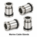
- Marine Cable Glands – Brass and nickel-plated cable glands for marine applications
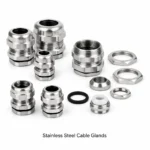
- Stainless Steel Cable Glands – SS 316 cable glands for corrosive environments
- Aluminium Cable Glands – Lightweight cable glands for weight-critical installations
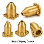
- Brass Wiping Glands – For paper-insulated lead-covered (PILC) cables
- Earth Tags Brass – Standalone brass earth tags for BW-type gland assemblies
- Brass Lock Nuts – Metric and NPT lock nuts for all cable gland types
- PVC Shrouds for Cable Glands – UV-stabilised protective shrouds for cable tails
- Thread Reducers and Adapters – Metric and NPT thread adapters for panel entries
Request a Quote
Electrical Accessories India supplies Brass CET Glands (Central Earth Termination cable glands) to electrical OEMs, EPC contractors, power utilities, marine engineers, and MRO distributors worldwide. Price: US$ 15.50 per kilogram (Ex-works Jamnagar, India). SKU codes EAI-CET-M20-NB through EAI-CET-M63-NB (metric) and EAI-CET-NPT12-NB through EAI-CET-NPT2-NB (NPT).
Email: sales@elecaccs.com | Phone: +91-22-43449300 | +91-22-43449323 | Contact Form