

Product
Product Details
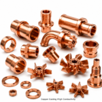
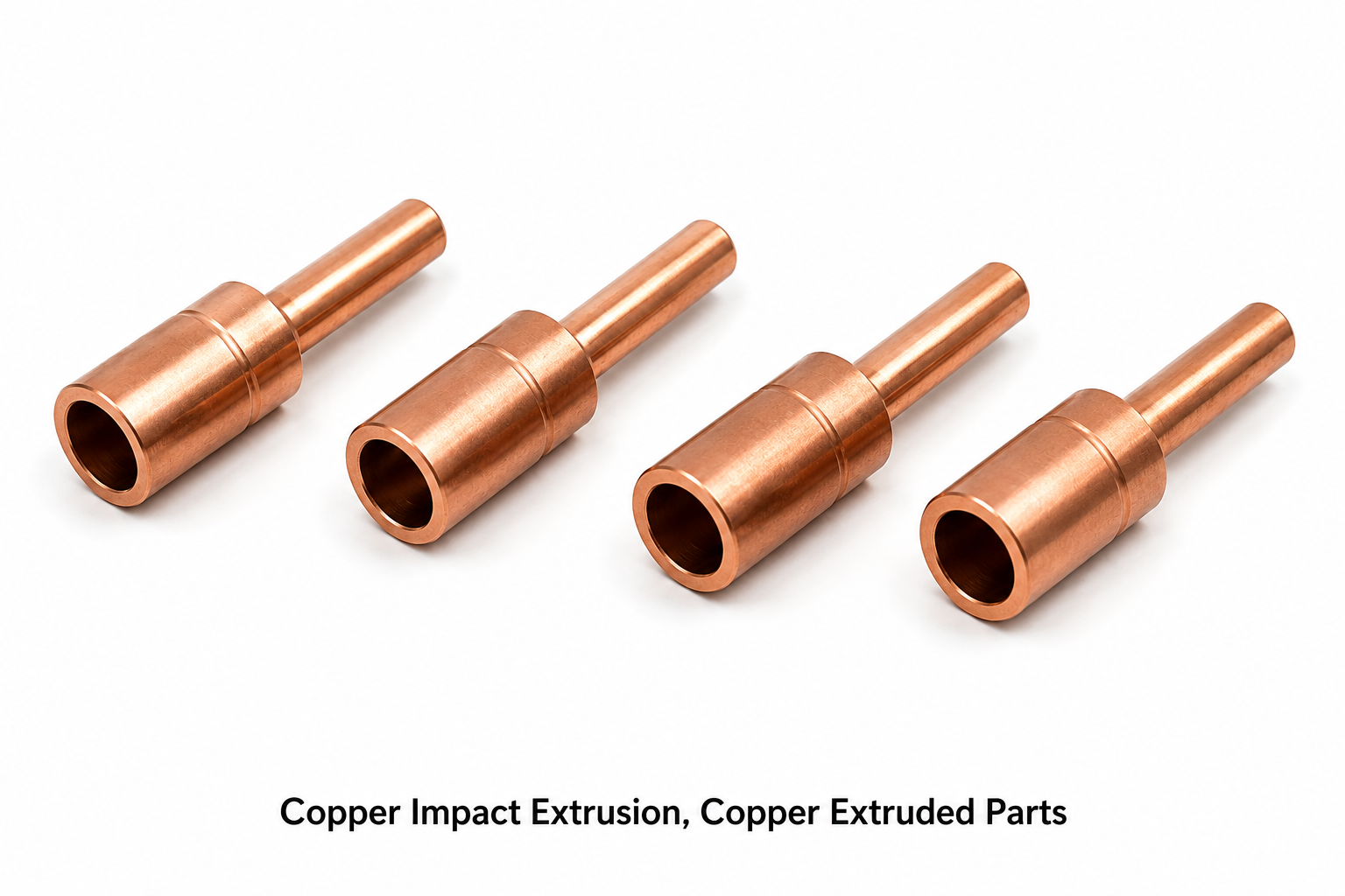
Copper Impact Extrusion, Copper Extruded Parts
Copper Impact Extrusion | Copper Extruded Parts
Pricing: US$ 15.80 / Kilogram (FOB India | MOQ: 50 Kg | Custom tooling available)
Electrical Accessories India manufactures copper impact extrusion parts and copper extruded parts using high-tonnage cold impact extrusion presses and continuous extrusion (Conform) processes. Produced from copper slugs of C11000 (ETP), C12200 (DHP), and C14500 (tellurium copper), these near-net-shape components include electrical connector shells, terminal caps, contact housings, cable end sleeves, hollow cylindrical parts, stepped tubes, and precision cup-shaped components. Impact extrusion enables complex axisymmetric geometries in a single stroke, with material utilisation ≥95%, eliminating machining waste and reducing per-piece cost significantly versus conventional CNC machining for medium-to-high volume production runs.
Product Overview – Copper Impact Extrusion and Copper Extruded Parts
Copper impact extrusion parts—also procured as copper cold-extruded components, copper impact-formed shells, copper slug extrusions, copper hollow extrusions, copper forward extrusions, copper backward extrusions, copper combined extrusions, and copper extruded profiles—are produced by forcing a copper slug (blank) through a hardened die under high press force (typically 50–1,000 tonnes) at ambient temperature (cold extrusion). The process produces a part with superior surface finish (Ra 0.8–1.6 µm), tight dimensional tolerances (±0.05 mm on diameter, ±0.1 mm on length), and improved mechanical properties due to work-hardening during deformation.
Impact Extrusion vs. Conventional Machining: For hollow, thin-walled, or cup-shaped copper parts, impact extrusion is 3–5× more cost-effective than machining from solid bar stock, with material utilisation rising from ~40% (machined) to ≥95% (extruded). Wall thickness uniformity of ±0.1 mm is achievable in single-stroke backward extrusion, making the process ideal for high-volume production of connector shells, terminal housings, and cable end fittings used in electrical assemblies.
Forward Extrusion: Used to produce solid or hollow rods, stepped shafts, and electrical pins. The copper slug is pushed through a reducing die, elongating the material to the desired cross-section. Forward extrusion produces parts with excellent axial straightness and concentricity—critical for electrical contact pins, connector inserts, and precision shafts in instrument components.
Backward (Indirect) Extrusion: The primary method for cup-shaped, sleeve, and shell components. The punch penetrates the stationary slug, forcing material backward around the punch to form a hollow cylindrical wall. Backward extrusion achieves wall thickness from 0.5 mm to 10 mm and part lengths up to 150 mm in a single press stroke, enabling efficient production of cable end sleeves, terminal caps, and connector bodies.
Combined (Forward + Backward) Extrusion: Produces flanged cups, stepped sleeves, and parts with internal and external profile changes in one stroke. Used for complex electrical connector housings, coaxial cable connectors, and relay contact assemblies where multiple geometric features are required simultaneously.
Continuous Extrusion (Conform Process): For long copper profiles, bus-bar sections, contact rail segments, and round/rectangular extruded rod, the Conform continuous extrusion process uses a rotating wheel and die to produce semi-finished copper shapes from rod or granule feed. Copper profiles for bus-bar distribution systems, electrical contact rail, and EV charging connector bodies are produced by this method.
Post-Extrusion Operations: Extruded copper parts routinely undergo trimming, piercing, coining, thread rolling, CNC turning for precision dimensions, electroplating (tin, nickel, silver), and heat treatment (annealing at 300–500 °C to restore ductility) as secondary operations. Complete sub-assemblies with pressed-in contacts or crimped terminals are offered.
Key Features
- Near-net-shape production: material utilisation ≥95% vs. ~40% for machining
- Press force range: 50–1,000 tonnes on dedicated copper extrusion presses
- Wall thickness: 0.5 mm minimum (backward extrusion)
- Dimensional tolerance: ±0.05 mm diameter, ±0.1 mm length
- Surface finish: Ra 0.8–1.6 µm (as-extruded)
- Work-hardened microstructure improves tensile strength 15–25%
- High volume capability: up to 50,000 pieces/day per press
- ISO 9001:2015 certified; tooling and die storage for repeat orders
Near-Net-Shape Economy
Impact extrusion is the most material-efficient cold-forming process for axisymmetric copper parts. A copper slug cut from extruded rod is formed into the final shape with material utilisation ≥95%, compared to 40–60% for machined-from-bar production. For electrical connector shells at 10 g each produced in volumes of 100,000 pieces/month, the raw material saving alone (at US$ 15.80/kg copper price) represents significant cost reduction—typically 30–50% lower piece cost vs. CNC machining for parts with length-to-diameter ratios above 2:1.
Superior Work-Hardened Properties
Cold impact extrusion work-hardens the copper, increasing tensile strength from ~220 MPa (annealed C11000) to 300–380 MPa (H80 temper) without any alloying additions. The elongated, fibrous grain structure produced by extrusion improves fatigue life and resistance to creep relaxation at elevated temperatures—critical properties for electrical terminal contacts that experience thermal cycling in service. Parts can be annealed post-extrusion to restore full ductility for crimping or subsequent forming operations.
Tooling and Die Life
Extrusion dies are manufactured from tungsten carbide (WC) or powder metallurgy tool steel (M2, D2) with TiN or TiAlN PVD coating to maximise die life in copper extrusion—typically 200,000–500,000 strokes per die set for ETP copper. Die design uses finite element analysis (FEA) simulation (DEFORM, QForm) to optimise metal flow, reduce extrusion force, and minimise die wear. Customer tooling is stored and maintained at our facility for repeat production runs at no additional tooling charge after amortisation.
Dimensional Repeatability
Statistical process control (SPC) monitoring of critical dimensions (outer diameter, wall thickness, length, and flange diameter) is performed every 500 strokes using calibrated gauge instruments. Cp/Cpk ≥1.33 is maintained on all critical dimensions. In-line vision systems detect and eject out-of-tolerance parts and surface defects (cracks, laps, cold shuts) automatically, ensuring defect rates below 200 ppm in full production.
Surface Treatment and Plating
As-extruded copper parts are degreased, pickled (dilute H₂SO₄ or HNO₃), and either supplied in bright natural copper finish or electroplated. Tin plating (ASTM B545, 2–8 µm) is the most common finish for electrical connector shells, providing oxidation resistance and solderability. Silver plating (ASTM B700, 5–25 µm) is specified for high-current contact caps and terminal adapters in switchgear. Nickel underplating (1–3 µm) is used beneath tin or silver on copper to prevent tin-copper intermetallic diffusion (tin whisker mitigation per JEDEC JESD201).
Custom Tooling Development
New part tooling (die set + punch + ejector) is developed from customer 2D/3D drawings using FEA-based process simulation to predict metal flow, extrusion force, and potential defects before physical die manufacture. Tooling lead time is typically 3–5 weeks. First-off sample parts are submitted for customer dimensional and functional approval before production release. Design modifications are accommodated with rework to existing dies where geometry permits, minimising tooling investment for design iterations during new product development.
Technical Specifications
| Parameter | Specification |
|---|---|
| Process | Cold Impact Extrusion (Forward, Backward, Combined), Continuous Extrusion (Conform) |
| Material Grades | C11000 (ETP), C12200 (DHP), C14500 (Te-Cu) |
| Blank/Slug Diameter | 8 mm to 80 mm |
| Part OD Range | 8 mm to 100 mm |
| Part Length Range | 5 mm to 200 mm |
| Min Wall Thickness | 0.5 mm (backward extrusion) |
| Diameter Tolerance | ±0.05 mm (as-extruded) | ±0.01 mm (post-machined) |
| Surface Finish | Ra 0.8–1.6 µm (as-extruded) |
| Press Force | 50–1,000 tonnes |
| Production Volume | Up to 50,000 pieces/day/press |
| Lead Time | 3–5 weeks (new tooling) | 2–3 weeks (existing tooling) |
| Price | US$ 15.80 / Kilogram (FOB India) |
Copper Grade Equivalents – Extrusion
| UNS (USA) | EN (Europe) | BS (UK) | DIN (Germany) | IS (India) | Description |
|---|---|---|---|---|---|
| C11000 | CW004A | C101 | E-Cu58 | ETP Copper | Electrolytic Tough Pitch – standard extrusion grade |
| C12200 | CW024A | C106 | SF-Cu | DHP Copper | Phosphorus Deoxidized – for welded/brazed assemblies |
| C14500 | CW118C | C109 | CuTeP | — | Tellurium Copper – free-machining post-extrusion |
Product Types / Variants
| Type | Description | Application |
|---|---|---|
| Cup / Shell (Backward Extrusion) | Hollow cylindrical cups with closed base | Connector shells, terminal caps, contact housings |
| Solid Rod / Pin (Forward Extrusion) | Solid stepped or straight rods | Contact pins, electrical studs, precision shafts |
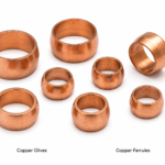
| Flanged Cup (Combined Extrusion) | Cup with integral flange for retention | Cable ferrules, terminal fittings, insulator caps |
| Tubular Sleeve | Open-ended thin-wall tube | Cable end sleeves, earthing pipe connections |
| Extruded Bus-Bar Section | Rectangular, round, or shaped copper profile | Bus-bar systems, contact rail, earthing strips |
| Multi-Flange Body | Complex stepped and flanged geometry | HV connector bodies, cable gland shells |
Applications by Industry
| Industry | Copper Extruded Part Application |
|---|---|
| Electrical Connectors and Terminals | Connector shells, terminal caps, socket housings, crimp ferrules |
| Switchgear and Panel Boards | Bus-bar end caps, contact tulips, plug-in connectors |
| Automotive and EV | HV connector housings, battery terminal adapters, shielding sleeves |
| Power Cables | Cable end sleeves, compression lugs, ferrule bodies |
| Renewable Energy | Solar MC4 connector bodies, wind turbine slip-ring segments |
| Telecommunications | RF coaxial connector bodies, waveguide flanges, EMI shielding cans |
| Railways and Traction | Contact wire clamp bodies, catenary connector shells |
Manufacturing Process
(1) Slug Preparation – copper rod is cut to precise slug weight on CNC slug cutters or saw-cut machines; slug weight determines extruded part volume and geometry. (2) Slug Annealing (if required) – at 450–600 °C to achieve maximum ductility for deep backward extrusions. (3) Lubrication – phosphate + soap, oil, or zinc stearate lubricant applied to slug and die for friction reduction and surface quality. (4) Extrusion Pressing – slug placed in die cavity; punch descends at controlled velocity; extrusion completed in single stroke (cold impact). (5) Trimming and Piercing – flash removed, base pierced to open hollow parts. (6) Post-Extrusion Machining – CNC turning to final dimensions on critical interfaces. (7) Plating and Surface Treatment – per customer specification. (8) Inspection and Documentation – dimensional sampling per AQL 1.0, SPC data recording, and certificate package preparation.
Quality Standards and Certifications
| Standard | Scope |
|---|---|
| ISO 9001:2015 | Quality Management System |
| EN 10204 Type 3.1 | Material test certificates |
| ASTM B187 / BS EN 13601 | Copper rod composition |
| ASTM B545 / IEC 60068-2-52 | Tin plating and salt mist testing |
| RoHS 2 / REACH | Hazardous substance compliance |
| JEDEC JESD201 | Tin whisker mitigation (tin-plated parts) |
Why Choose Electrical Accessories India?
Our dedicated copper impact extrusion capability—with in-house die design, FEA simulation, and tooling manufacture—enables rapid new product introduction and competitive pricing for medium-to-high volume production. Key advantages: near-net-shape manufacturing for minimum material waste; in-house die storage for repeat orders; post-extrusion CNC machining on same site; competitive pricing at US$ 15.80/kg FOB India; and full documentation per EN 10204 3.1. We export to USA, UK, Germany, UAE, Australia, and Southeast Asia.
Frequently Asked Questions
Q1. What is the minimum wall thickness achievable in copper backward extrusion?
Minimum wall thickness of 0.5 mm is achievable for small parts (OD ≤ 20 mm). For larger parts (OD 50–100 mm), minimum practical wall thickness is 1.0–1.5 mm, depending on part length, copper grade, and press force available.
Q2. How long does tooling development take?
New tooling design, simulation, and manufacture typically takes 3–5 weeks. First-off samples are submitted within 1 week of tooling completion. Simple rotationally symmetric parts with existing similar die configurations can be tooled in 2 weeks.
Q3. What is the typical lot size for copper impact extrusion?
Economic lot sizes start from 500 pieces for simple shapes with existing die configurations, or 1,000 pieces for new tooling amortisation at standard pricing. For strategic supply programs, blanket orders of 50,000–500,000 pieces/year with scheduled monthly releases are preferred.
Q4. Can extruded parts be further machined?
Yes. Post-extrusion CNC turning and drilling is standard for achieving tight tolerances (±0.01 mm) on specific interfaces, thread cutting, and drilling cross-holes. Combined extrusion + CNC machining delivers the lowest per-piece cost for complex copper components.
Q5. What surface treatments are available for copper extruded parts?
Bright copper, tin plating (ASTM B545), nickel plating, silver plating (ASTM B700), and zinc phosphate + oil (for unplated storage) are standard. Chemical passivation and lacquer coating are available for outdoor and tropical environment applications.
Q6. Are copper extruded profiles (bus-bar sections) available?
Yes. Rectangular, round, and custom-profiled copper bus-bar sections are produced by the Conform continuous extrusion process from copper rod or granule feed. Hardness and temper (annealed, half-hard, hard) are controlled to EN 13601 specifications.
Q7. Do you accept designs with FEA simulation reports?
Yes. We welcome customer FEA simulation data and can review die fill predictions from DEFORM or FORGE software. We also perform in-house FEA validation of our own die designs before physical die manufacture to minimise first-off tooling failures.
Q8. What packaging is used for copper extruded parts?
Parts are packed in VCI (Volatile Corrosion Inhibitor) polybags with desiccant, inner divider trays for plated parts, and outer corrugated cartons. Bulk packing in intermediate bulk containers (IBCs) is available for large quantity production shipments.
Multilingual Equivalent Terms
| Language | Equivalent Terms |
|---|---|
| Spanish | Extrusión por impacto de cobre, Piezas extruidas de cobre, Componentes extruidos en cobre |
| Russian | Медные детали холодного выдавливания, Экструдированные медные компоненты, Медные прессованные детали |
| French | Extrusion par impact du cuivre, Pièces extrudées en cuivre, Composants cuivre filés |
| Portuguese | Extrusão por impacto de cobre, Peças extrudadas de cobre, Componentes cobre extrudidos |
| Italian | Estrusione per impatto del rame, Parti estruse in rame, Componenti rame estrusi |
Related Products – Copper Parts and Components
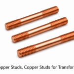
- Copper Transformer Studs
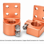
- Copper Transformer Stud Connectors
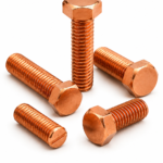
- Copper Hex Bolts, Copper Bolts
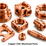
- Copper CNC Machined Parts
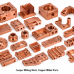
- Copper Milling Work / Copper Milled Parts
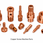
- Copper Screw Machine Parts
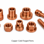
- Copper Cold Forged Parts
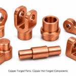
- Copper Forged Parts / Copper Hot Forged Components
- Copper Sealing Washers
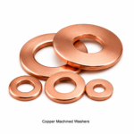
- Copper Machined Washers
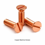
- Copper Machine Screws
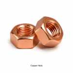
- Copper Nuts
- Copper Casting High Conductivity
- Copper Sealing Washers
- Copper Machined Washers
- Copper Machine Screws
- Copper Nuts
- Copper Casting High Conductivity
Request a Quote
Electrical Accessories India | Manufacturer & Exporter of Copper Impact Extrusion Parts
📧 Email: info@elecaccs.com | 🌐 elecaccs.com
📦 Price: US$ 15.80 / Kilogram (FOB India) | Tooling: 3–5 weeks | Production: 2–3 weeks | MOQ: 500 pcs